
Apollo 600 Setting Up Instructions
Please check the following:
(1) Adjust Helmet Suspension. |
|
(2) Check that the lens system is in place. |
The respirator assembly must never be used without the fixed inner lens, intermediate lens and the outer lenses! |
(3) Air Supply Hose. |
Use integral handle to carry the respirator. Never hold, carry or hang the respirator by the breathing hose! |
Air Supply
Air supply to this respirator system is a critical component for the safety of the user and is not included in this delivery. Read this section carefully. Poor quality air will cause serious respiratory injury or death to the user (see 2.2).
Air Quality
The quality of air supplied to the respirator is extremely critical to the safety of the user. Special care must also be taken to avoid accidental connection to any other gas lines, such as oxygen, acetylene or nitrogen.
Never connect a breathing air-line to an air source that has not been tested for gas and particulate contamination.
Do not use piston type (oil bath) compressors for breathing air. These compressors may produce dangerous levels of carbon monoxide.
The presence of unacceptable levels of carbon monoxide (CO) or other gases in the breathing air can cause death to the user.
Breathing air must be only used in following conditions:
- Breathing air used to supply the respirator must be respirable breathing air and is not allowed to contain less than 19,5 % by volume of oxygen.
- Prior to using the respirator, read the owner’s manual and all instructions, labels, and warnings related to the compressed air source. Take special care about all the statements and warnings from the compressor supplier.
- If an oil-lubricated compressor is used, it must be equipped with a high-temperature alarm or carbon monoxide (CO) alarm, or both. If only a high temperature alarm is used, that air from the compressor must be tested frequently for the presence of carbon monoxide. The user is responsible for the inspection of the breathing air, the compressor, the alarm system for carbon monoxide, the Air Filter and wear of the instruments. A compressor which is too hot or was not maintained properly can produce carbon monoxide or a bad smell. To assure a good quality of breathing air you can also use systems to remove or to convert the carbon monoxide. The maximum permitted concentration of CO2 in breathing air is 10ppm (parts per 1,000,000).
- Regardless of the air compressor type, precautions must be taken to prevent contaminants from entering through the compressor intake. The compressor inlet must be located away from all sources of toxic contaminants including carbon monoxide which is found in engine exhaust and in any form of combustion. No vehicles should be allowed near the compressor intake.
- The precautions described above also apply to portable compressors. In addition, in the case of engine-driven compressors, precautions must be taken to prevent engine exhaust gases from entering the air intake of the compressor. Compressor engine exhaust should be piped to a location safely downwind from the compressor air intake. Compressors may vary in design and operation.
- A fitted Air Filter like the CPF-20 Filter, must be connected and maintained regularly to filter bad smells, oil mist, condensed water, rust from pipes and other contents.
Air Volume Velocity, Pressure and Hose Length
The quantity of air needed from a blaster for having enough oxygen to breathe is between
130 l/min ... 190 l/min.
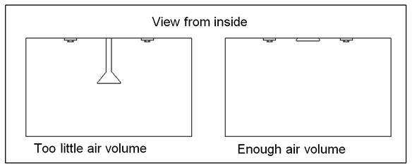
This minimum supply ensures that the volume indicator is functioning, i.e the flag is retracted – otherwise the flag falls down into view.
Use only CE-approved hoses with safety couplings between the air filter and the control valve (see section 11 – spare parts).
The maximum hose length between the filter and the control valve can be 40m. If it is necessary to use longer hoses you have to contact the manufacturer to take appropriate measures.
The maximum pressure at the supply hose is 8 bar.